Dash Colour Change
Printed From: rsvr.net Forums
Category: RSV / RSVR / FACTORY
Forum Name: 'How To Guides'
Forum Description: A compilation of guides and advice from forum members
URL: http://www.rsvr.net/forum_posts.asp?TID=4558
Printed Date: 27 Mar 2026 at 00:30
Software Version: Web Wiz Forums 12.07 - https://www.webwizforums.com
Topic: Dash Colour Change
Posted By: amb67
Subject: Dash Colour Change
Date Posted: 17 Dec 2009 at 22:32
|
How to Change the LCD Dash Illumination Colour Please be warned that if you do this mod you do so at your own risk and there is great potential to destroy your LCD dash in the process. You will need to be able to solder well and should not attempt this modification unless you understand basic electrics. I changed my LCD dash illumination to blue to match my bike and also because I have pretty poor colour perception and find it hard to see black on an orange background. The whole modification takes around an hour or so to complete, including removing the front fairing. First of all you will need some LED’s in whatever colour you want the LCD dash to be illuminated in. I used some surface mounted LED’s as they are small have low power consumption and generate no heat at all. 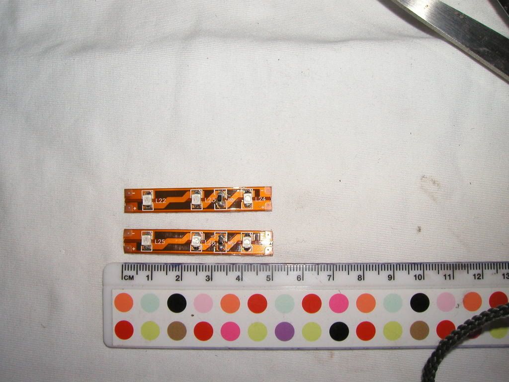 You can buy them from here - http://www.led-depot.co.uk/epages/es111582.sf/en_GB/?ObjectPath=/Shops/es111582_shop/Products/Blue%20SMD%20Flexible%20Strip/SubProducts/Blue%20SMD%20Flexible%20Strip%201m - LED Depot I would suggest that if a group of you are doing this modification then buy a 1 metre strip and share it around, it works out very cheap that way. You will need two strips of 3 LED’s per strip for each LCD unit. (That’s four 5cm strips in total) You will also need some coloured transparent film; I again used blue to achieve the desired effect. I obtained mine off a guy on EBAY USA as I struggled to find anyone who could supply the colour I wanted in the UK. This is the guy I purchased mine off http://stores.ebay.co.uk/Paper-Street-Plastics - Paper Street Plastics You only need two pieces to cover the back of the LCD units, a sheet 15cm x 15cm would be ample. (This allows some extra just in case it all goes wrong) OK, you now have to source some small gauge wire; I used an old telephone cable wire that was lying around. You’ll only need a small amount, the bit I used was around a metre long and I have some left over. OK, let’s get started on how to modify your dash display colour: 1. Remove your front fairing so you can see this: 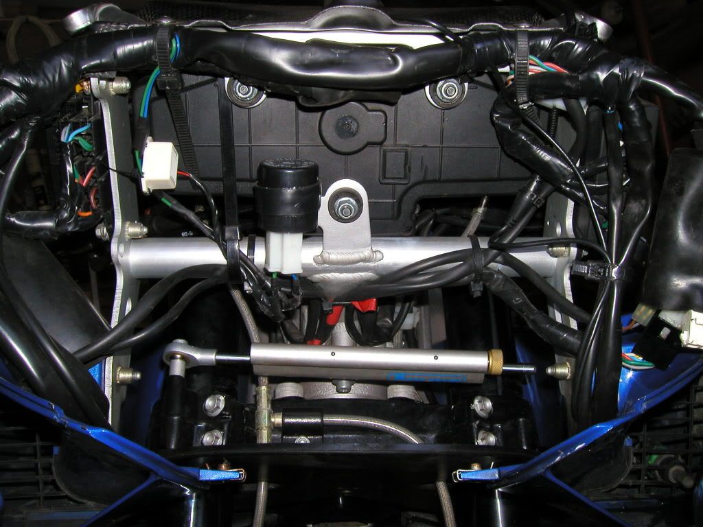 2. The next step is to remove the dash from the bike. This is done by removing the three 10mm nuts and washers from here. 3. Don’t forget to remove the multi plug before trying to rip the dash out of the mounts: 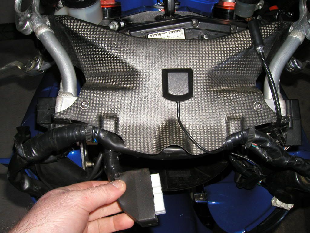 4. Carefully extract the dash from the gap between the headstock and the upper dash cover: 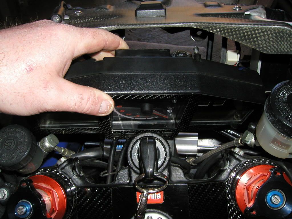 5. Place the dash face down on a clean piece of cloth so you can ensure that no scratching of the face occurs during the next few stages. 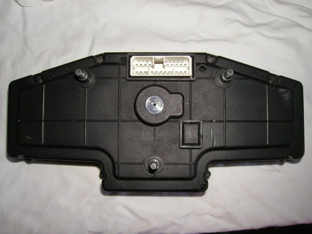 6. Now remove the 8 small screws holding the rear dash cover in place. 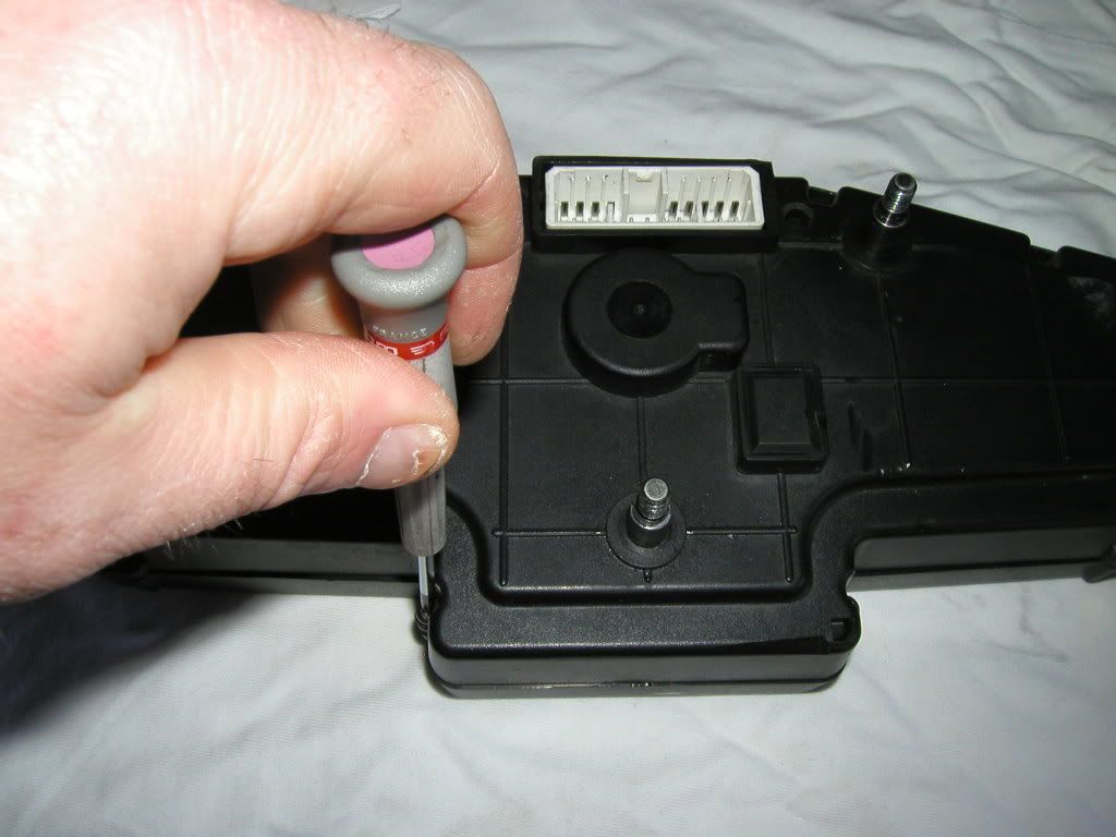 7. Remove the rear dash cover to expose the PCB (Printed Circuit Board). 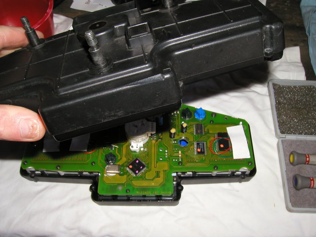 8. Next step is to remove the PCB from the front cover: 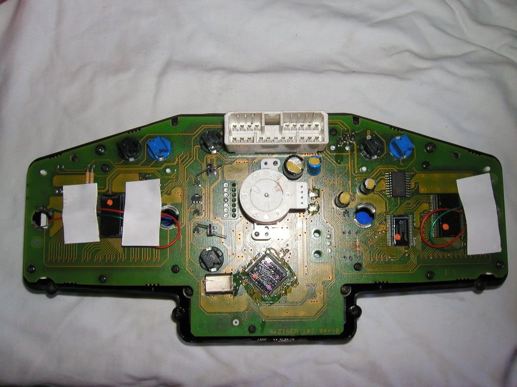 To remove the PCB unscrew the four small screws here. Once undone, remove the screws and carefully lift out the PCB from the dash front cover. 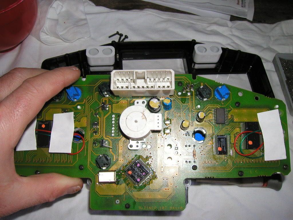 9. Next job is to remove the LCD display from the PCB: 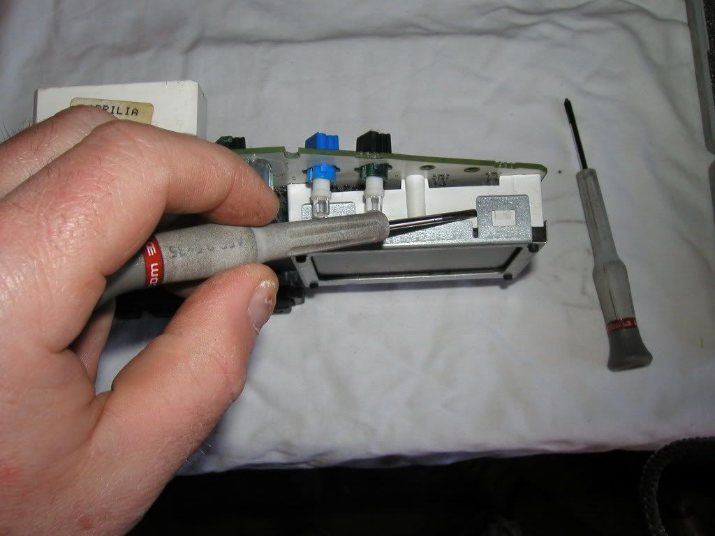 This done by carefully sliding a small flat bladed screwdriver under the metal tags thus allowing the LCD display along with the metal case to be slowly extracted from the dash unit. Make sure you don’t extract it at an angle or you could damage the LCD zebra strip that supplies the power to the LCD. Once removed it will look like this (Less the LED’s that I had already fitted) 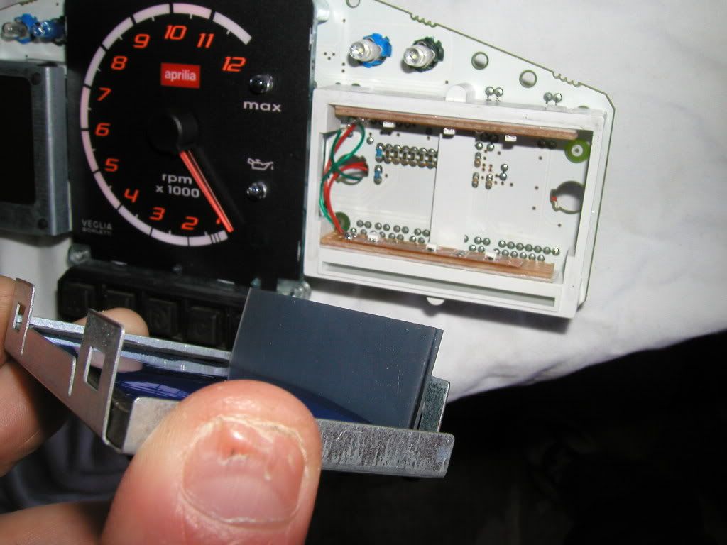 10. Now you can add the colour film to the rear of the LCD, cut it slightly larger than the visible LCD so that you can tuck it under the rubber edge mount. 11. Next step is to build the LED’s: 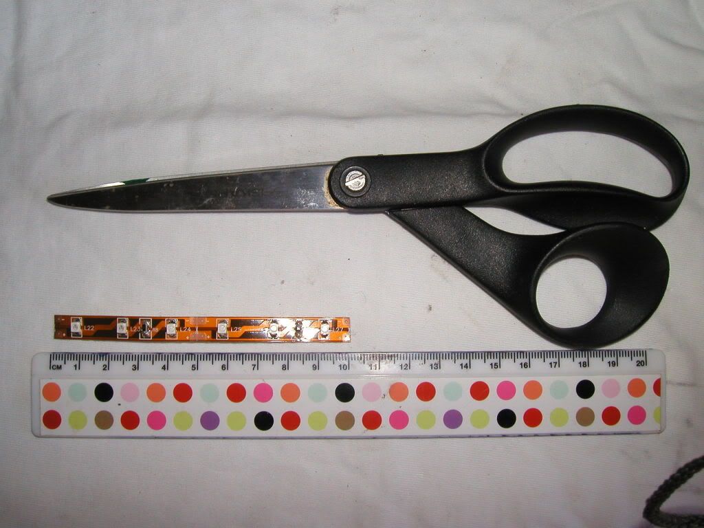 Mine arrived like this and had to be cut to size, there is a small symbol on the strip that shows a picture of a pair of scissors, only cut at these points. If you cut elsewhere you will destroy the LED strip and most likely your dash too. 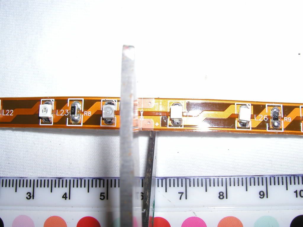 12. Cut the wire so that you have two lengths per LCD (e.g. You will need 4 for a complete dash) in different colours at least 10cm long. You will also need two lengths around 20cm long of different colours. 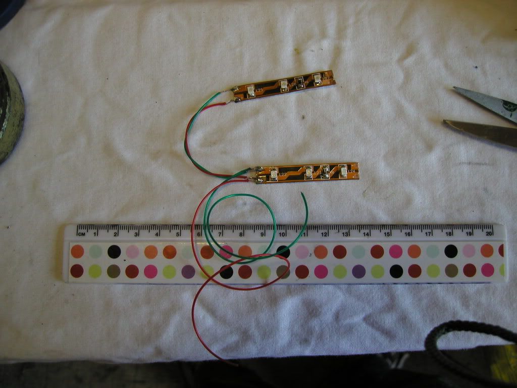 The aim here is to connect both negatives of each strip to one negative wire and both positives of each strip to one positive wire. 13. What you have to do now is mount them in the dash frame like this: 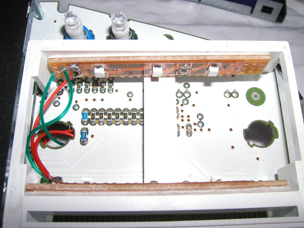 As you can see from this shot I had mounted mine on some Vero board to lower them in the frame to give a more direct light. In hindsight this is not really a good idea as you want the LED’s to be masked slightly to produce a more even lighting effect. Before you peel off the backing on the LED strips to reveal the self adhesive part, clean the surface of the dash to what you’re going to stick the LED strip to. Simply push the two wires that will form the negative and positive feeds for the LED strips through the previous backlight bulbs hole. 14. Before you go soldering the positive and negative feeds in you need to test them and make sure the LED’s light up. This is done by taking the dash over to the bike, plug it in to the connector you removed earlier, switch on the ignition and then simply touch the wires on the power supply surfaces now exposed due to removal of the backlight bulb carriers. 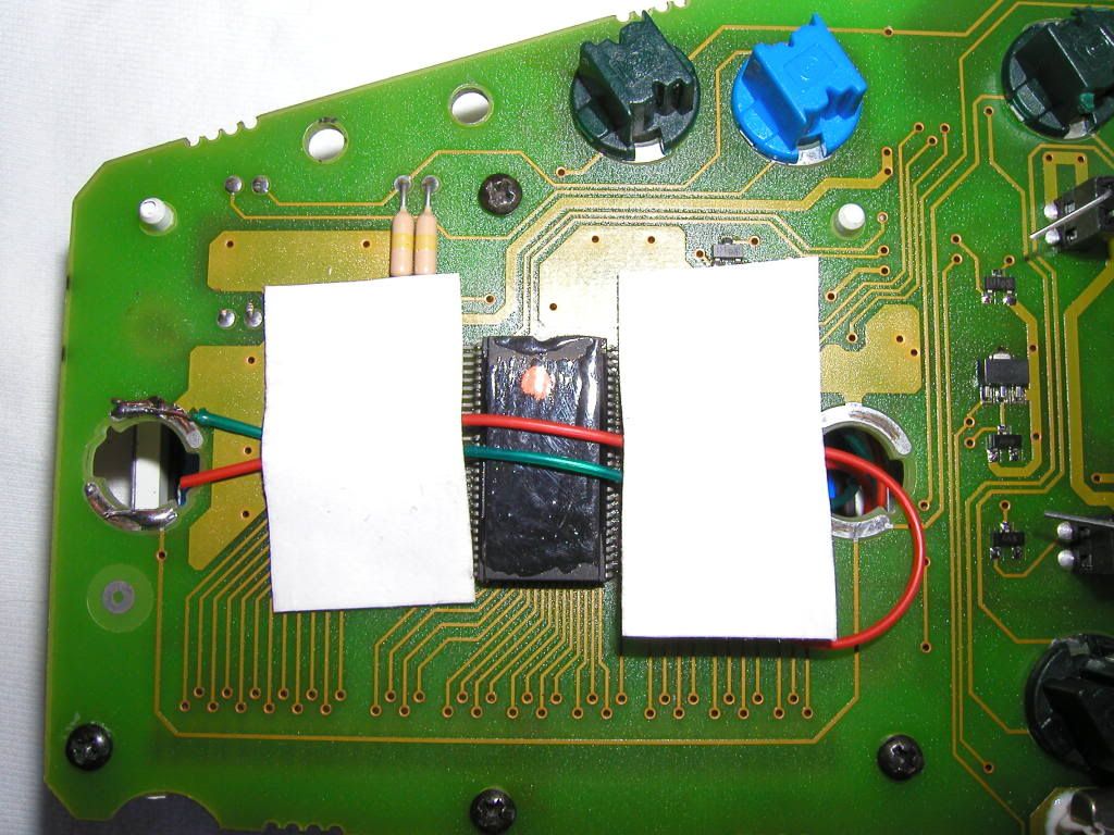 Make sure you have the light switch set to the on position otherwise it won’t work at all. Once you have it so that it illuminates with the light switch in the on position and powers down when in the off position, then secure in place with solder. 15. OK that’s all done now all we have to do is rebuild. Do not remove the dash from the bike at this stage as you need to test it still. Insert the LCD display back in to the dash unit and make sure that those metal tags you prised apart earlier make a secure connection with the dash frame. Once it’s back in its location then turn on the ignition and make sure that all the digits etc... work and that the back light works too. If some digits don’t work, do not panic, turn the ignition off, remove the LCD unit and simply refit again ensuring that the LCD is pushed in firmly where the zebra connector is. Complete the rebuild in reverse order of what you did when you removed the parts and the job is completed. This was my finished product: 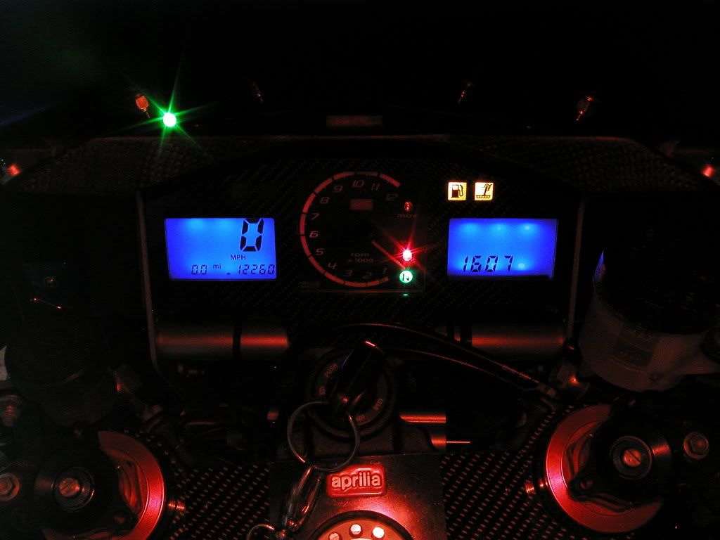 -------------  Blue ones are so much faster than black ones. |
Replies:
Posted By: camngetit
Date Posted: 06 Dec 2012 at 23:11
|
Bit late but if you do this you can use blue led bulbs , but whichever way you need to remove the orange filters off the screens , they are Greyish on the back and you need to go under the black seal round the edge otherwise it will stay orange whatever you do ------------- its twins for me !!!! www.apriliaperformance.co.uk www.apriliaforum.co.uk www.apriliaownersclub.co.uk |
Posted By: Sabre
Date Posted: 07 Dec 2012 at 09:28
  This is mine.
 -------------  |
Posted By: NickyBoy1984
Date Posted: 07 Dec 2012 at 13:33
That looks proper ace  NickyBoy  ------------- www.rsvr.net www.apriliaperformance.co.uk www.apriliaforum.co.uk www.apriliaownersclub.co.uk |
Posted By: kiwi_rsvr
Date Posted: 07 Dec 2012 at 18:26
Stu mate the second hand has fallen off the Sabre clock !! - Although I know you IFA's love charging by the hour 
|
Posted By: Throbbing-Twin
Date Posted: 06 Feb 2014 at 21:17
|
Tempted to try this. Is it the same for all models as I have a 98 gen1 ------------- If its not broken then fix it until it is |
Posted By: Spoonz
Date Posted: 06 Feb 2014 at 21:22
| Same for all Gen 1 yes. Only change on those was a green to orange backlight around 2001 |
Posted By: Throbbing-Twin
Date Posted: 06 Feb 2014 at 21:43
Cheers. Another mod to put on the list lol. I find the green a bit boring. ------------- If its not broken then fix it until it is |
 Spoonz wrote:
Posted By: camngetit
Date Posted: 06 Feb 2014 at 23:51
|
Easier with led replacement bulbs and don't forget to remove the orange filters under the black edge seal ------------- its twins for me !!!! www.apriliaperformance.co.uk www.apriliaforum.co.uk www.apriliaownersclub.co.uk |
Posted By: Mooro
Date Posted: 07 Feb 2014 at 09:06
What does the orange filter look like ?? if i'm being a noob and thinking a piece of plastic/paper type thingy could you not just get a different filter sheet and place that in there ?? ------------- www.apriliaperformance.co.uk www.apriliaownersclub.co.uk www.apriliaforum.co.uk www.rsvr.net |
Posted By: camngetit
Date Posted: 01 Mar 2014 at 19:51
|
It's quite thick and looks grey on the back I used some blue film aswell as the LEDs ------------- its twins for me !!!! www.apriliaperformance.co.uk www.apriliaforum.co.uk www.apriliaownersclub.co.uk |
Posted By: rsvwalt
Date Posted: 06 Apr 2018 at 12:17
| have you still got these photos, the backlight on the rhs of my dash has failed and if the speedo side goes I'll need to change them, thanks |
Posted By: Spoonz
Date Posted: 06 Apr 2018 at 13:54
Chances of multiple bulbs failing at the same time is pretty slim. Did the backlight all go at once and have you checked the bulbs ?
|
Posted By: redratbike
Date Posted: 06 Apr 2018 at 18:13
-------------  |
Posted By: rsvwalt
Date Posted: 06 Apr 2018 at 21:51
| ive found a post on the aprilia forum, I hadn't got a clue what they look like inside but I can see now and will leave it until winter if none of the others go out. Thanks for the replies. |